

Fiber Laser Marking Machine
Fiber Laser Marking Machine
Discover our fiber laser marking machine with 30W–100W power options, high-speed marking up to 7,000 mm/s, and precise marking for industrial applications.
Category -> Machines and Spare Parts
Description
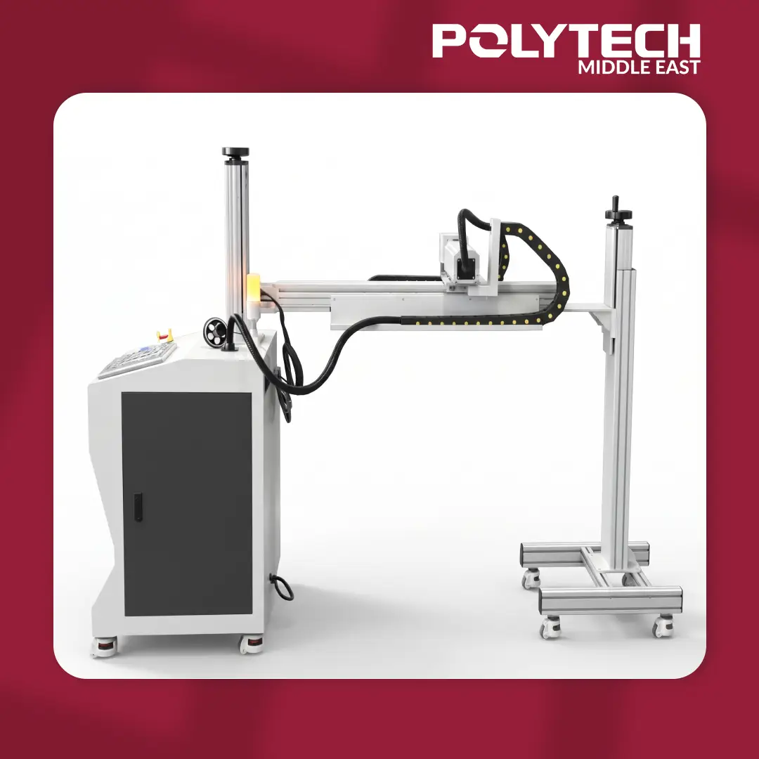
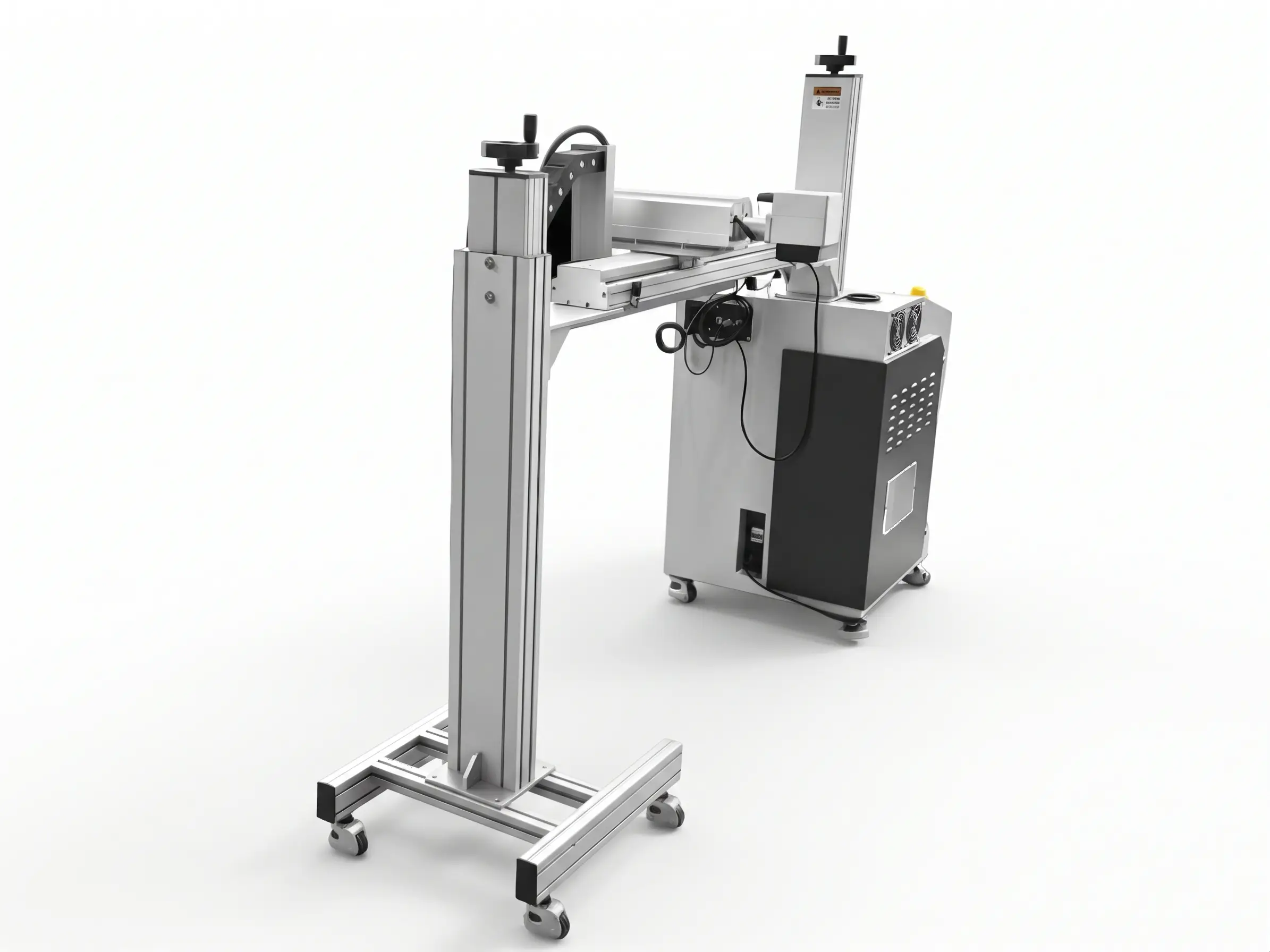
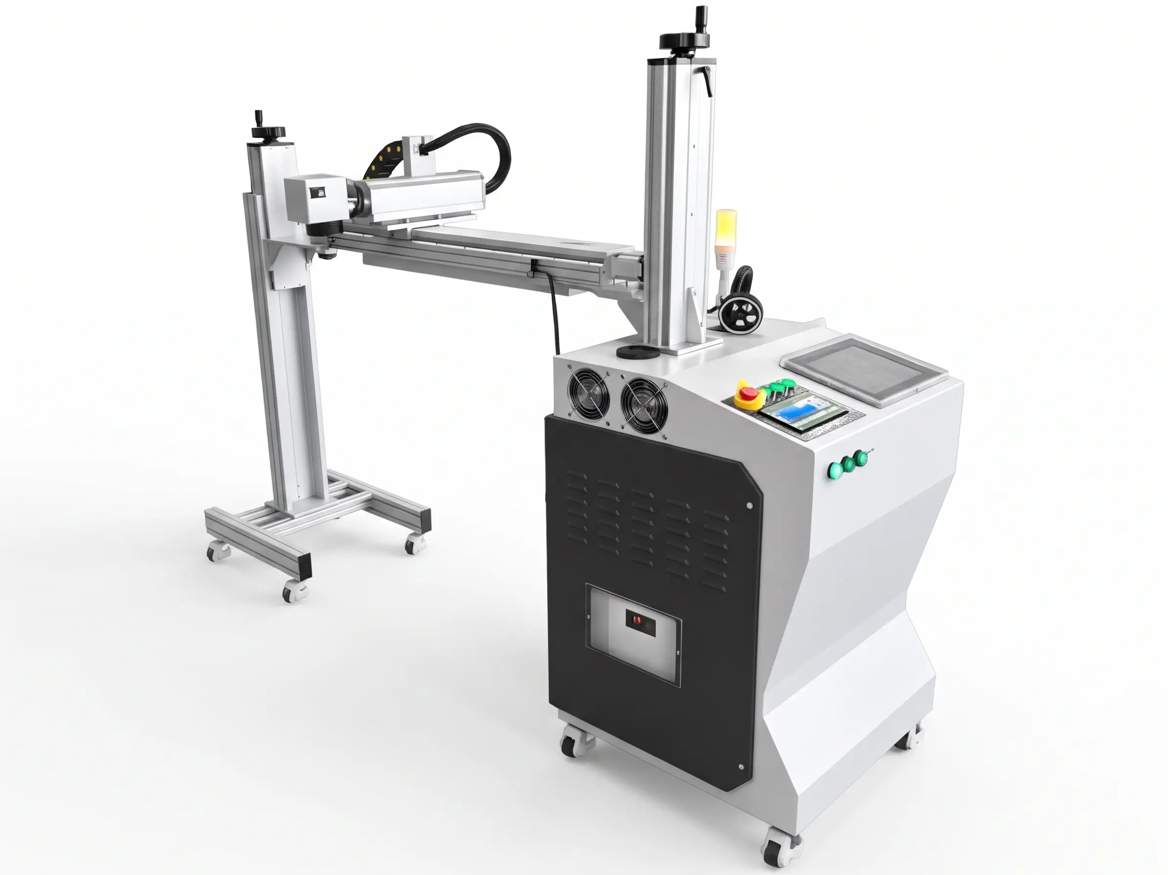
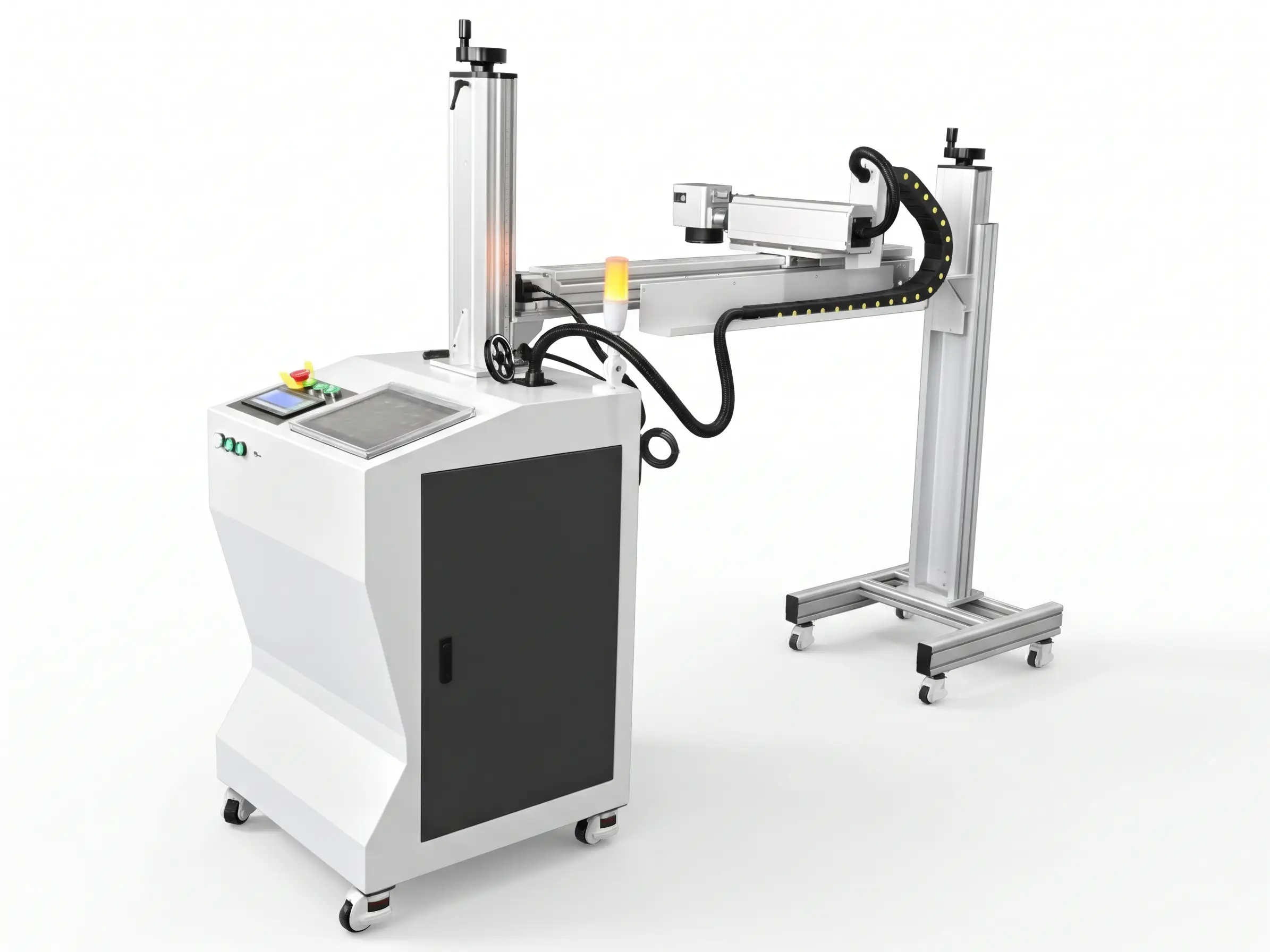
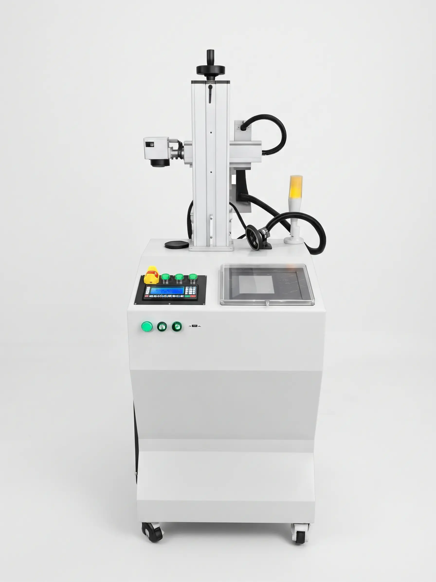
The Fiber Laser Marking Machine is an industrial marking solution designed to create clear, precise, and durable markings on compatible materials. Equipped with a Raycus laser source, a JHC galvanometer scanner, and a CNF-130 control system, this machine combines reliable laser technology with efficient marking capabilities for industrial production environments.
With available laser power options of 30W, 50W, 60W, and 100W, the machine can be configured to meet different marking requirements. It is suitable for applications involving product identification, serial numbers, logos, barcodes, QR codes, and other markings, depending on the material and selected settings.
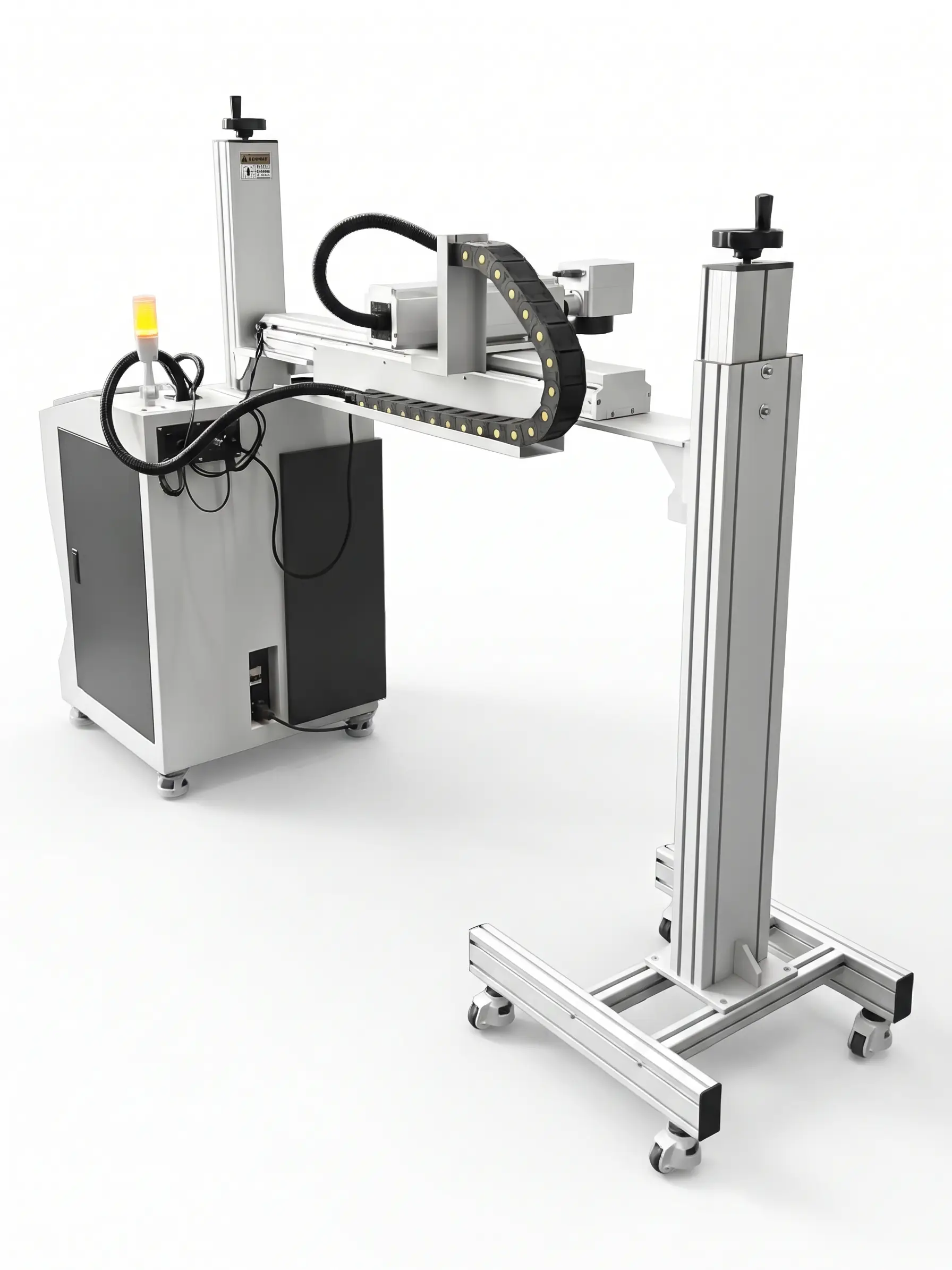
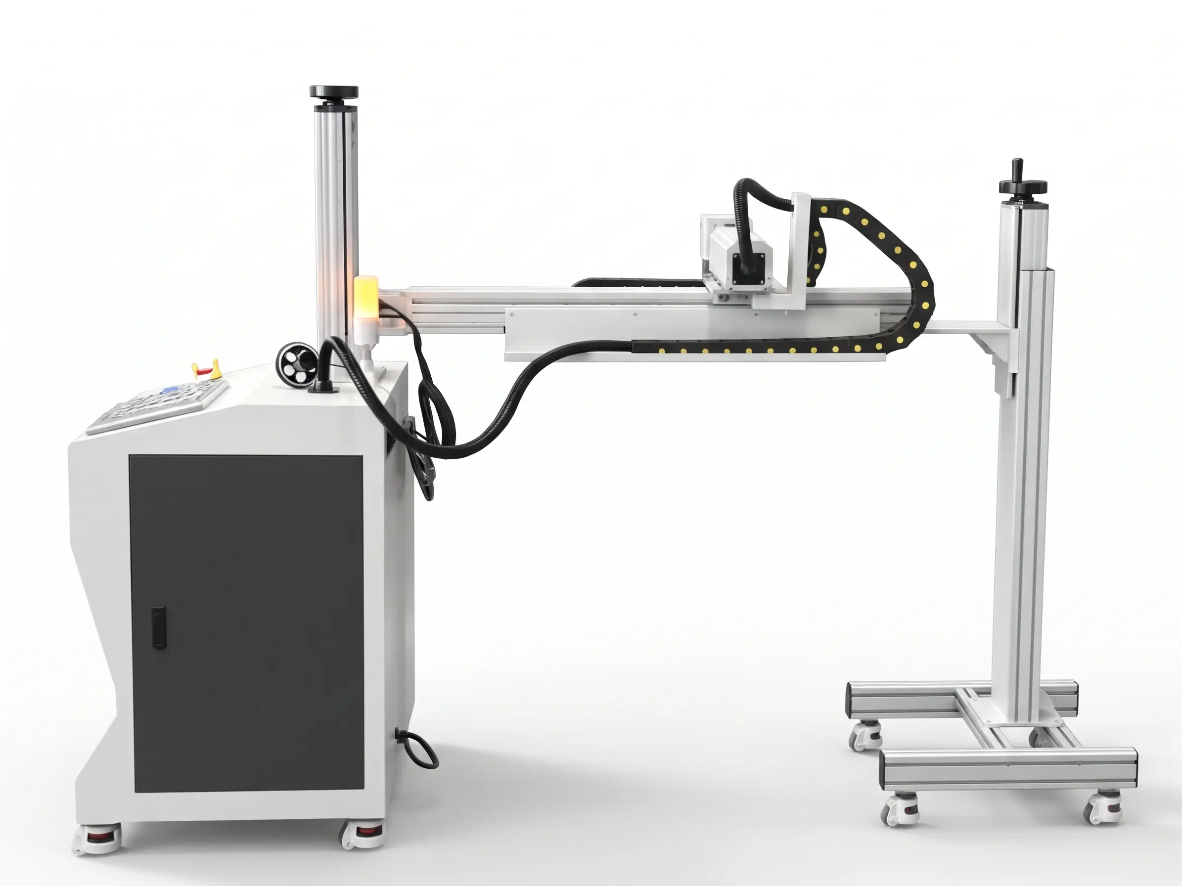
The machine features a compact control cabinet, an adjustable marking head assembly, and a working area available in 110 × 110 mm and 150 × 150 mm configurations. Its marking speed is specified at up to 7,000 mm/s, making it a potential solution for manufacturers seeking an efficient marking process for industrial components and products.
Designed for integration into manufacturing workflows, the Fiber Laser Marking Machine offers a practical combination of marking precision, configurable laser power, and convenient operation.
Key Features of the Fiber Laser Marking Machine
Raycus Laser Source
The machine uses a Raycus laser source to generate the laser beam required for marking applications.
A fiber laser source is commonly used in industrial marking because it can produce fine details and consistent markings on compatible materials. Its suitability for a specific application depends on the material composition, surface condition, marking depth, and selected laser parameters.
Multiple Laser Power Options
The Fiber Laser Marking Machine is available in four laser power configurations:
- 30W
- 50W
- 60W
- 100W
These options allow manufacturers to select a configuration according to their marking requirements. Lower-power configurations may be suitable for many standard identification and surface-marking tasks, while higher-power options can provide greater processing capability for certain applications. However, actual performance depends on the material, marking method, required depth, and operating parameters. Choosing the appropriate laser power helps balance marking quality, processing time, and application requirements.
High-Speed Marking Performance
The machine has a specified marking speed of up to 7,000 mm/s.
High-speed laser marking can help improve production efficiency when marking large numbers of components or applying repetitive product information. Actual production throughput depends on the marking content, material, required contrast, component handling time, and machine settings. For manufacturers with recurring marking tasks, the system can support efficient processing when properly configured for the application.
JHC Galvanometer Scanning System
The machine incorporates a JHC galvanometer scanner that directs the laser beam across the designated marking area. Galvanometer scanning systems use controlled mirrors to position the laser beam rapidly, allowing text, graphics, and other marking patterns to be produced without moving the entire laser head across every point of the design. This technology is widely used in industrial laser marking because it supports fast scanning and detailed marking patterns.
High Marking Precision
The supplied specifications list a repeatability value of 0.01 mm.
Repeatability describes the ability of a system to reproduce a position or movement consistently. This specification should not automatically be interpreted as the guaranteed marking accuracy or minimum achievable line width. Actual marking quality depends on the optical system, material, laser parameters, focus, and the design being marked.
Flexible Working Area
The machine offers two working-area configurations:
- 110 × 110 mm: Standard configuration.
- 150 × 150 mm: Alternative configuration.
The working area determines the maximum field available for marking without repositioning the workpiece. A 110 × 110 mm field may be appropriate for smaller components and compact marking designs, while a 150 × 150 mm field provides a larger marking area for suitable applications. The appropriate configuration depends on the size of the product and the required marking dimensions.
Convenient USB Connectivity
The machine specifications identify USB as its interface. USB connectivity can support communication with compatible computers and control equipment, depending on the installed software and system configuration. This can help integrate the marking process into a production workflow where marking designs and product information are prepared digitally.
Compact Industrial Design
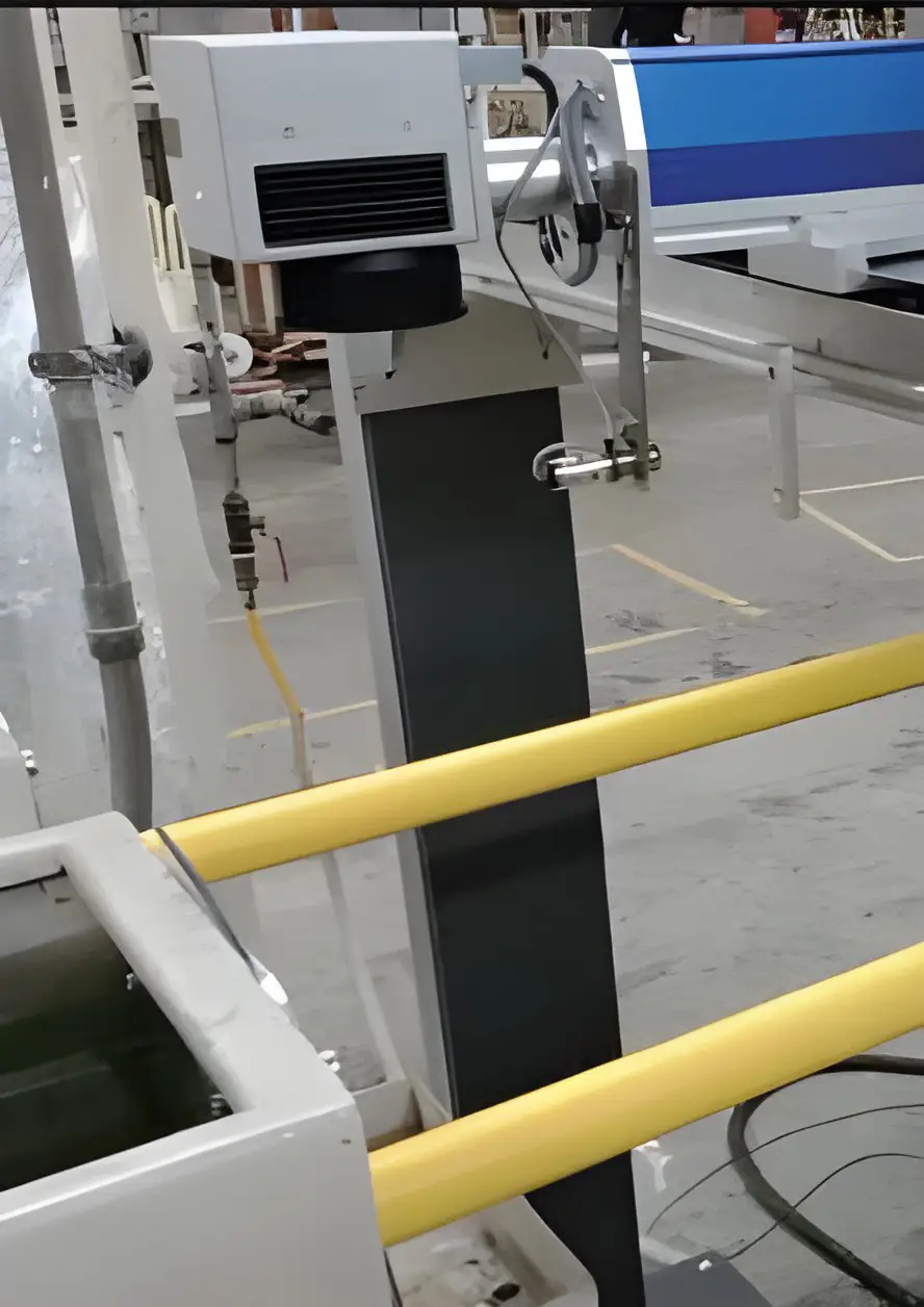
The machine features a dedicated control cabinet and a vertically adjustable marking-head assembly. Its overall dimensions are approximately 2163 × 620 × 1570 mm, with a listed weight of 100 kg. These specifications help manufacturers assess the installation space and handling requirements before integrating the machine into their production facilities.
How Does a Fiber Laser Marking Machine Work?
A Fiber Laser Marking Machine uses concentrated laser energy to create a visible mark on the surface of a compatible material. Depending on the material and process settings, the laser may change the surface appearance, create contrast, or remove a controlled amount of material. The marking process generally involves the following steps.
Step 1: Prepare the Product
The component to be marked is placed in the designated working area. Proper positioning helps ensure that the marking appears in the intended location and maintains the required orientation.
Step 2: Prepare the Marking Design
The required content is prepared using compatible marking software.
Depending on the application, the design may include:
- Company logos.
- Product names.
- Serial numbers.
- Manufacturing codes.
- QR codes and barcodes.
- Text and graphic elements.
The available functions depend on the machine’s control system and compatible software.
Step 3: Configure the Laser Parameters
The operator selects suitable settings for the material and marking requirements. Important parameters may include laser power, marking speed, frequency, pulse settings, and focus position, depending on the laser source and controller. Correct parameter selection is essential for achieving the desired contrast and marking quality.
Step 4: Execute the Marking Process
The galvanometer scanner directs the laser beam across the workpiece according to the programmed design. The interaction between the laser and the material produces the required mark. The resulting appearance depends on the material and the selected marking method.
Step 5: Inspect the Finished Mark
The finished component is checked to ensure that the marking is legible and correctly positioned. For applications involving serial numbers, traceability codes, or product identification, inspection helps verify that the marked information meets the production requirements.
Advantages of Fiber Laser Marking Technology
High-Speed Processing
Fiber laser marking supports rapid beam movement and can process many marking designs without conventional mechanical engraving tools. This makes the technology suitable for production environments where components require repeated identification or labeling.
Detailed and Consistent Markings
The focused laser beam can produce fine text, symbols, and graphics on compatible surfaces. When the machine is correctly configured, it can support consistent marking results across repeated production runs.
Non-Contact Processing
Laser marking does not require a conventional cutting or engraving tool to make physical contact with the workpiece. This can reduce mechanical tool wear associated with contact-based marking methods. However, the laser may still modify or remove surface material depending on the selected process.
Flexible Marking Content
Digital marking designs can be adapted to different products and identification requirements. Manufacturers can prepare different serial numbers, logos, codes, and text layouts, subject to the capabilities of the control software.
Support for Product Traceability
Marking unique identifiers directly onto components can help businesses track products through production and quality-control processes. The usefulness of this approach depends on marking durability, code readability, and the company’s traceability system.
Multiple Power Configurations
The availability of 30W, 50W, 60W, and 100W options allows the machine to be selected according to different application requirements. This flexibility can help manufacturers match the equipment to their expected marking tasks.
Products
Materials and Industrial Applications
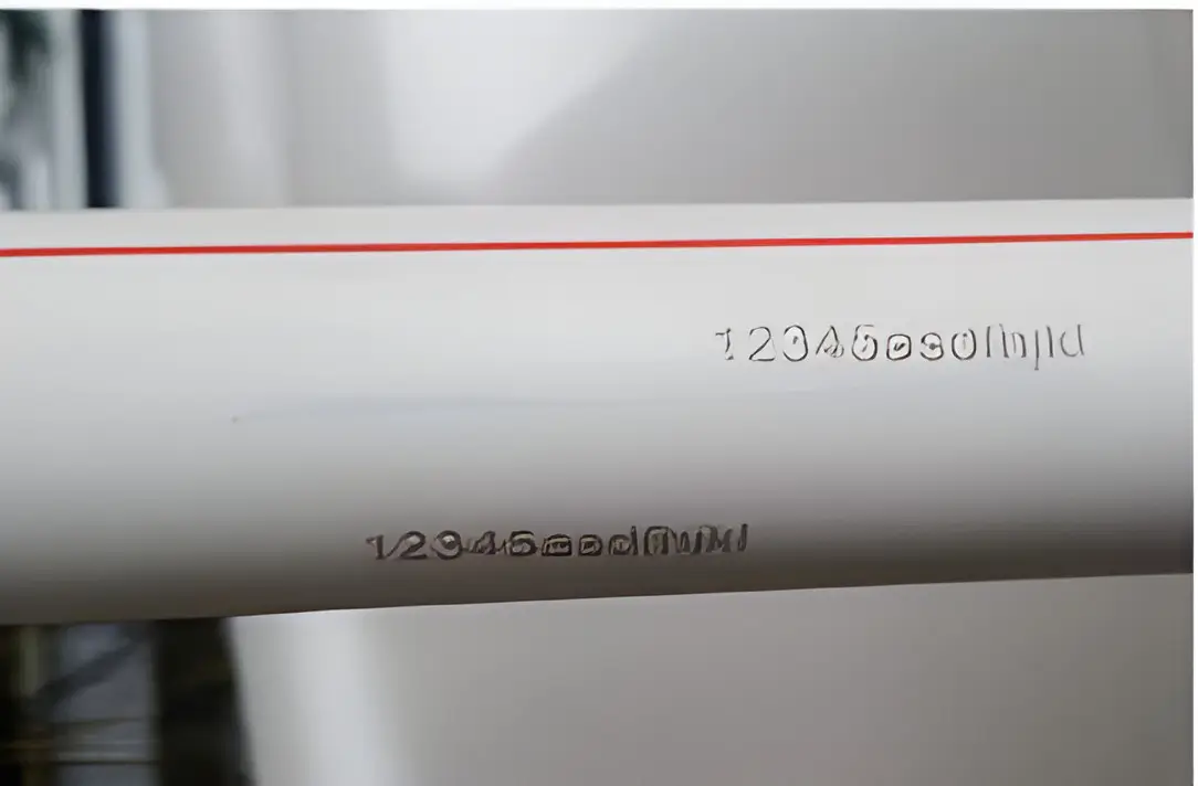
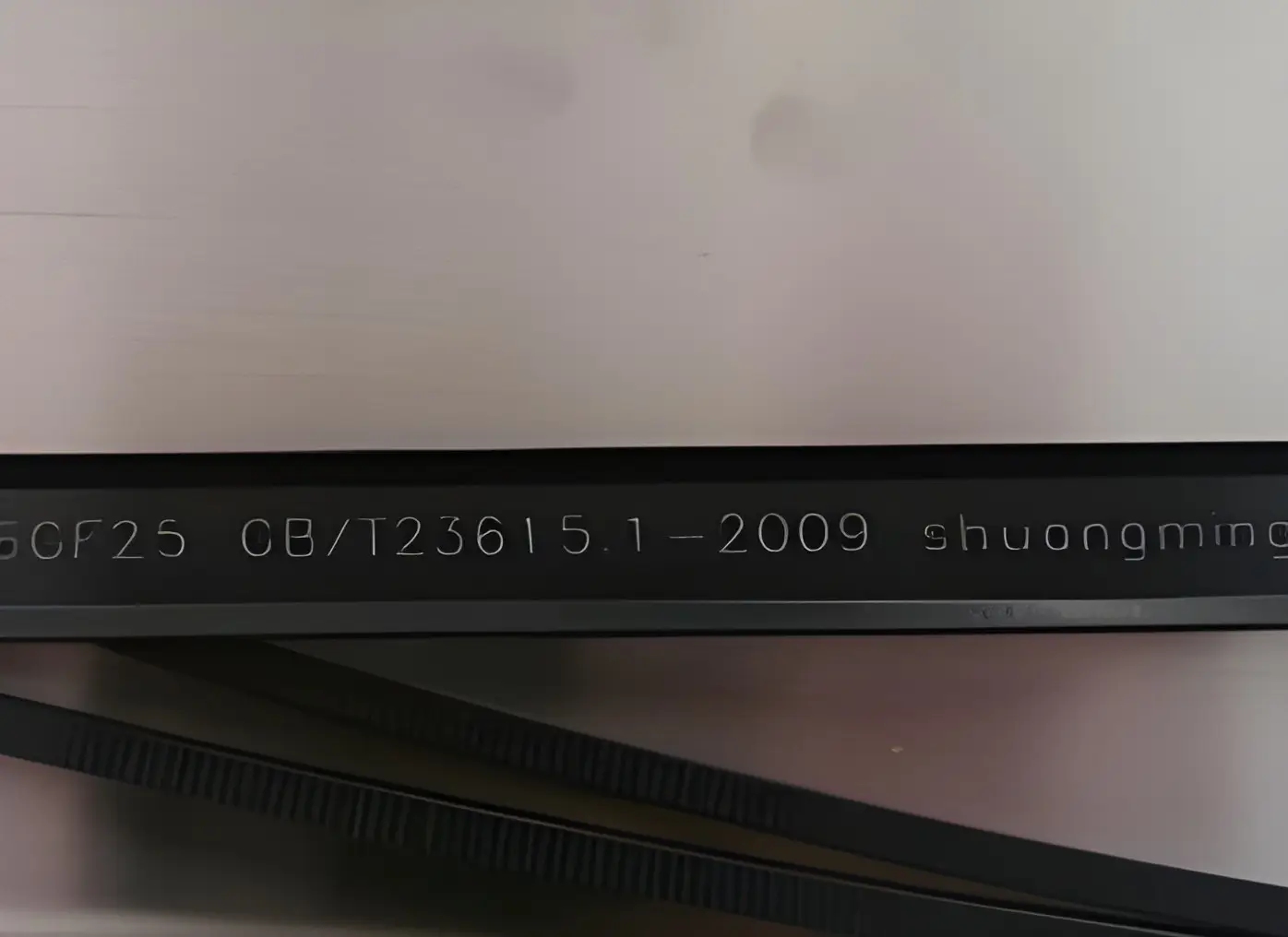
Fiber laser marking technology is commonly used for marking metals and certain other compatible materials. The exact material compatibility of this machine should be confirmed through testing and the manufacturer’s specifications.
Stainless Steel Marking
Stainless steel components are widely used in industrial equipment, machinery, tools, and fabricated products. A fiber laser marking system can create identification marks, text, logos, and other designs on suitable stainless steel surfaces. The final appearance depends on the marking parameters and whether the application requires surface marking, engraving, or a particular contrast effect.
Carbon Steel Marking
Carbon steel is used in machine components, metal parts, industrial tools, and fabricated structures. Laser marking can help manufacturers apply product codes, identification numbers, and other information directly to compatible carbon steel components. The marking settings should be selected according to the surface condition and required result.
Aluminum Marking
Aluminum is commonly used in industrial equipment, electronic housings, automotive components, and lightweight products. Fiber laser marking can be used for identification and branding on suitable aluminum surfaces. The marking appearance varies depending on the alloy, surface finish, and any anodized or coated layer.
Industrial Parts Identification
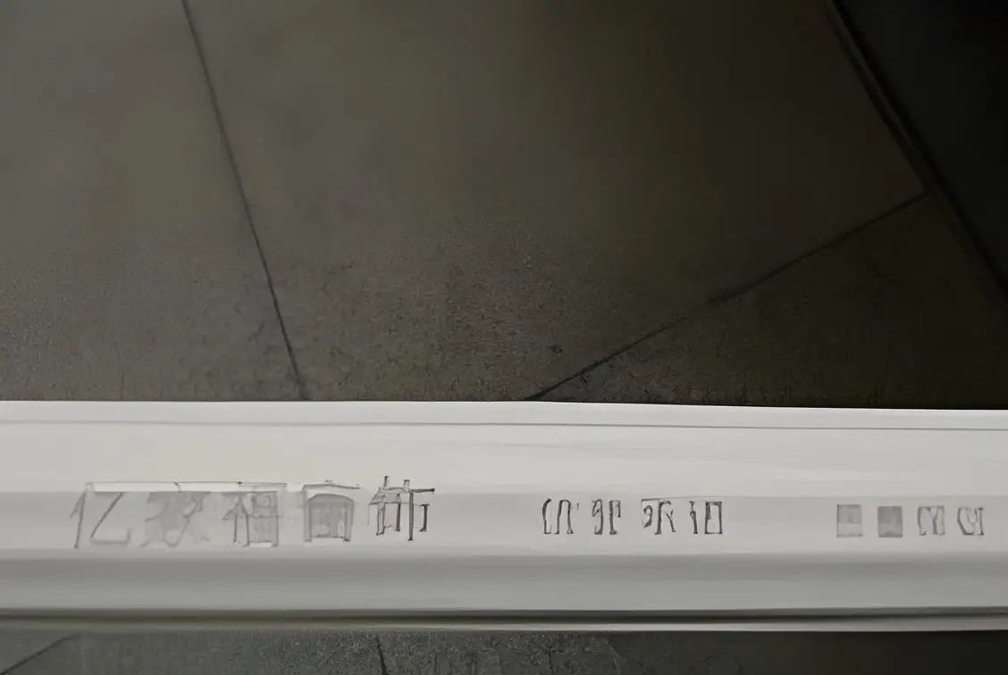
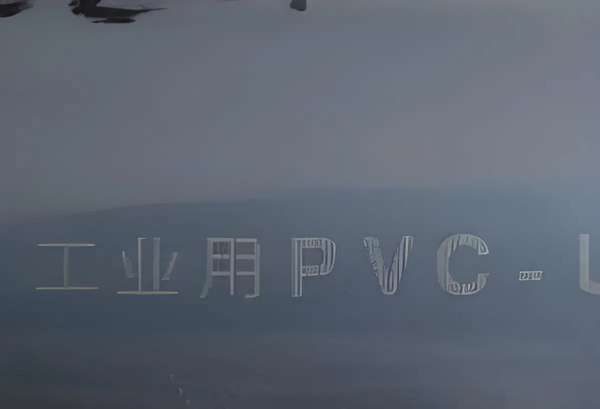
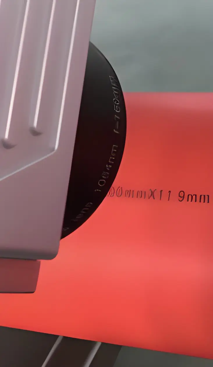
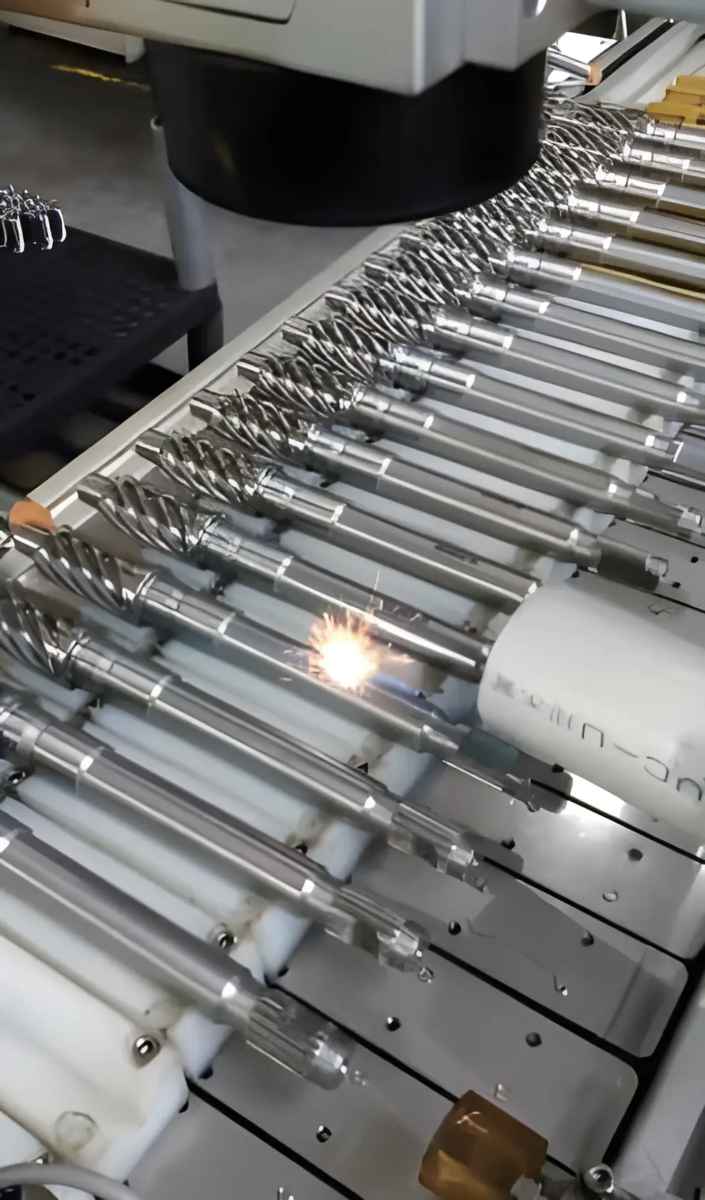
Product identification is an important application of industrial laser marking. Manufacturers can use the machine to mark part numbers, serial numbers, manufacturing information, and other identifiers on compatible components. Permanent or durable markings can support product identification throughout manufacturing, assembly, inspection, and distribution, depending on the marking method and operating environment.
Logo and Brand Marking
Laser marking can be used to apply logos, product names, and graphic designs to suitable products. This allows manufacturers to incorporate branding directly into components rather than relying exclusively on printed labels. The achievable detail and appearance depend on the material, optical configuration, and marking parameters.
Barcode and QR Code Marking
Barcodes and QR codes are commonly used for product identification, inventory management, and traceability. A fiber laser marking machine can produce these markings on compatible materials when the appropriate design and settings are used. For reliable scanning, the code size, contrast, surface condition, and marking quality must meet the requirements of the intended scanning system.
How to Choose the Right Fiber Laser Marking Machine Configuration
Selecting the appropriate configuration depends on the intended application and production requirements.
Consider the Material
Different metals and surface finishes respond differently to laser energy. Testing the actual material can help determine whether the required contrast, detail, and marking durability can be achieved.
Determine the Required Marking Area
The standard 110 × 110 mm working area may be suitable for smaller components, while the 150 × 150 mm option provides a larger field for suitable designs.The product dimensions and required marking position should guide this decision.
Select the Appropriate Laser Power
The available 30W, 50W, 60W, and 100W configurations provide different power options.The correct selection depends on the marking method, material, required processing time, and desired result. Higher power does not automatically guarantee better marking quality.
Evaluate Production Requirements
Manufacturers should consider the number of parts processed per shift, the complexity of the marking content, workpiece handling, and required traceability.These factors help determine whether the machine configuration is appropriate for the production workflow.
Confirm Software and Integration Requirements
Before purchasing, verify the supported marking software, operating-system compatibility, file formats, and communication interfaces.This helps ensure that the machine can work with the company’s existing product-design and production systems.
Get the Right Laser Marking Solution for Your Business
The Fiber Laser Marking Machine combines a Raycus laser source, JHC galvanometer scanner, and CNF-130 control system to provide a flexible solution for industrial marking applications.With 30W, 50W, 60W, and 100W power options, a choice of working areas, and a specified marking speed of up to 7,000 mm/s, the machine can be evaluated for a range of product identification and metal-marking requirements.Whether your business needs to mark serial numbers, product codes, logos, or other identification information, selecting the right configuration is essential for achieving the desired results.
Applications
Gallery
Main Features
Technical Specifications of the Fiber Laser Marking Machine
The following table summarizes the specifications provided in the supplied product image.
| Specification | Details |
| Machine Type | Fiber Laser Marking Machine |
| Laser Source | Raycus |
| Galvanometer Scanner | JHC |
| Power Supply | MW / HF / FC |
| Control System | CNF-130 |
| Laser Power | 30W / 50W / 60W / 100W |
| Laser Wavelength | 1064 nm |
| Marking Depth | ≤ 0.01 mm (as specified by the supplier) |
| Maximum Specified Marking Speed | ≤ 7,000 mm/s (as specified by the supplier) |
| Repeatability | 0.01 mm |
| Standard Working Area | 110 × 110 mm |
| Optional Working Area | 150 × 150 mm |
| Interface | USB |
| Protection Rating | IP45 |
| Weight | 100 kg |
| Machine Dimensions (L × W × H) | 2163 × 620 × 1570 mm |
Related products
-
 Machines and Spare Parts
Screws and Barrels for Extrusion
-
 Machines and Spare Parts
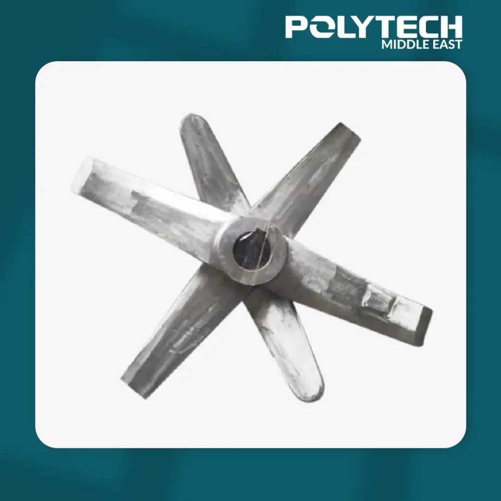
PVC Mixer Blades
-
 Machines and Spare Parts
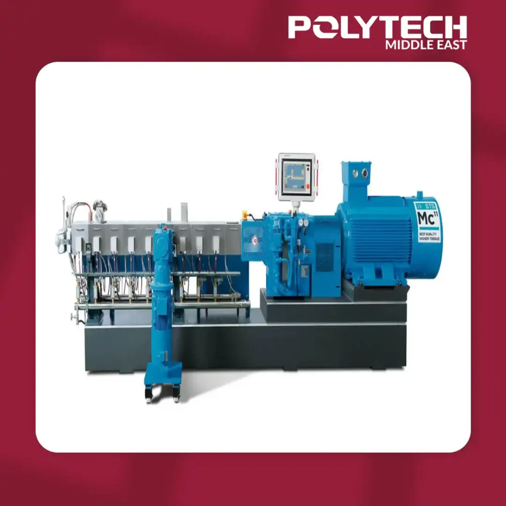
High-Torque Twin-Screw Extruder
-
 Machines and Spare Parts
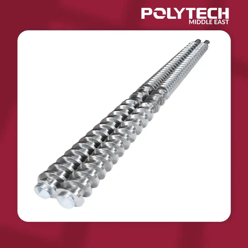
65/138 Conical Twin-Screw Barrel